2022 is when I went hog wild creating electronic projects. I kinda dabbled in stuff before, but something unlocked in my head and I just couldn't stop making new things. I think learning my way around KiCad was what really got the juices flowing.
tms-adapter
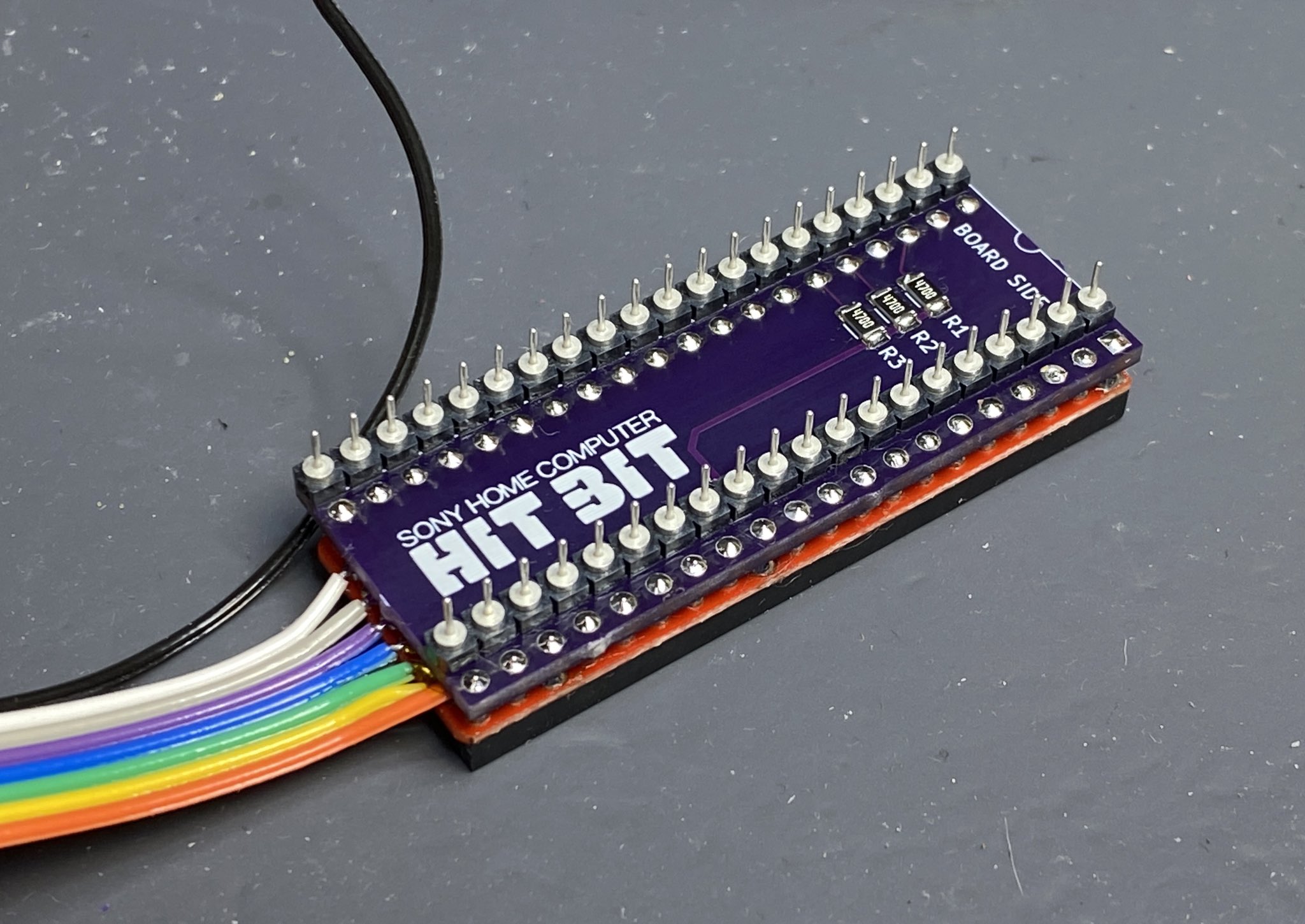
In 2021, I got a Sony HB-101 HitBit Mezzo MSX computer. It has composite out, and I wanted higher quality output. It is an absolutely beautiful computer and it felt like a shame that it was limited to composite video only. In 2022, I came across the TMS-RGB which lets you add RGB output to computers and consoles that use the TMS9128 VDP. Unfortunately the HB-101 has a TMS9118 VDP that has a different pinout and doesn't have the component output signals that the TMS-RGB requires. So I designed a little adapter board that let me plug in a TMS9128 into my HB-101 and routes the component signals to the proper pins for the TMS-RGB with the required resistors. I gave it the very creative name of tms-adapter. The design files are up on GitHub. It was written about on a Japanese MSX modder's blog, which I thought was pretty cool.
The adapter:
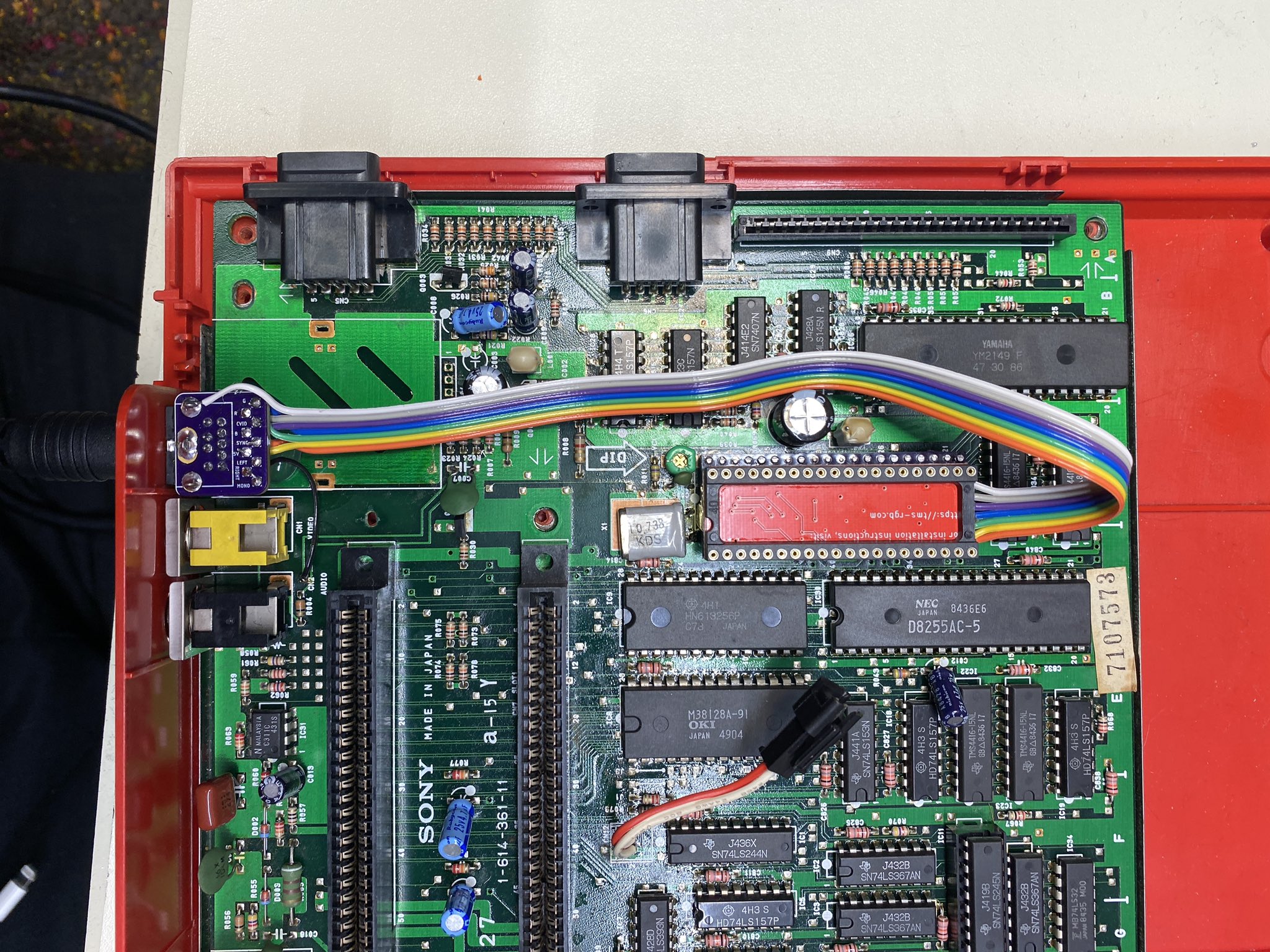
Installed in the HB-101:
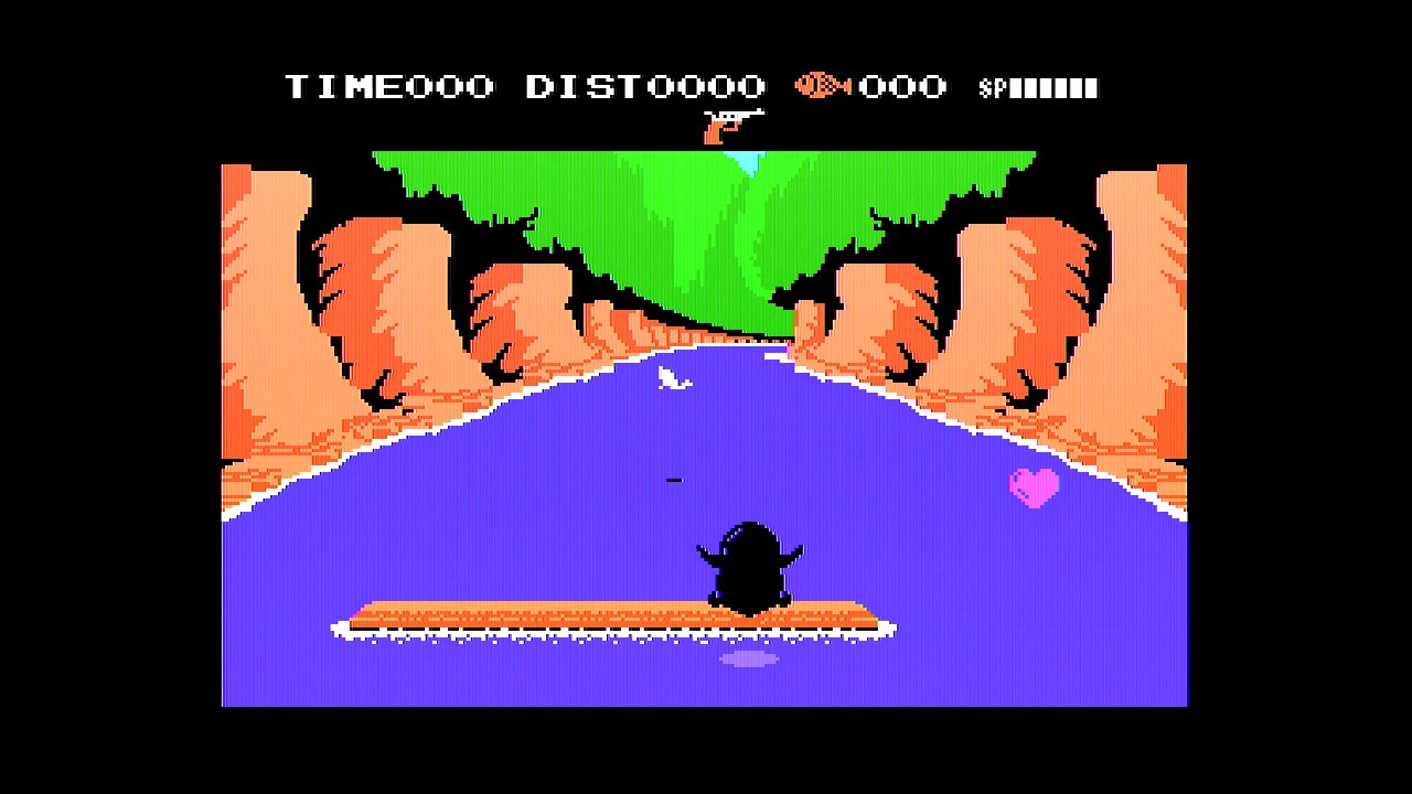
RGB output. Still some ringing but it's much cleaner than the composite:
MAC SCSI activity LED adapter
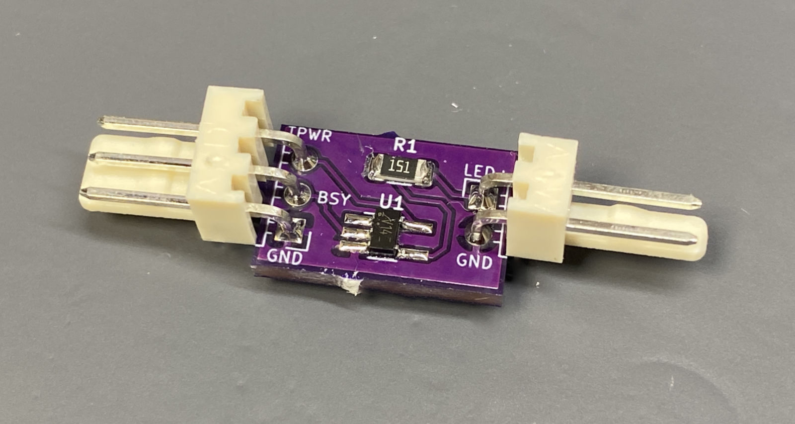
I've been restoring a number of classic compact Macintosh computers. I use a BlueSCSI to run the systems, plugged into the external DB25 SCSI port. Unfortunately this means that the internal hard drive activity light no longer works! I designed a tiny little adapter board to tap off the SCSI BSY signal, invert it, and drive the Mac's hard drive LED. Again, the design files are up on GitHub.
The board:
The blinking:
Amiga 1200 hard drive LED mixer thingy
In 2022, I brought back an Amiga 1200 from a trip to Scotland, along with a TerribleFire TF1260 accelerator board. The TF1260 has an IDE interface on it that's quite a bit faster than the Amiga's onboard interface, but it doesn't make the hard drive LED blink. I just can't let a hard drive LED go unblinking, so I started making a board that mixes the activity signal from the onboard IDE with the IDE on the TF1260. Unfortunately, this supposedly simple project went through six hardware revisions before I wound up with something that actually worked and drove the LED with enough current! I just had too much of a "digital logic" brain when designing it and wasn't thinking analog enough. Thankfully the helpful folks on the Retro Tinkering discord set me straight and I finally got something that worked. I was pretty humbled by this experience! I still need to get the design for this one up on GitHub...
Failed designs. These were based on NAND gates:
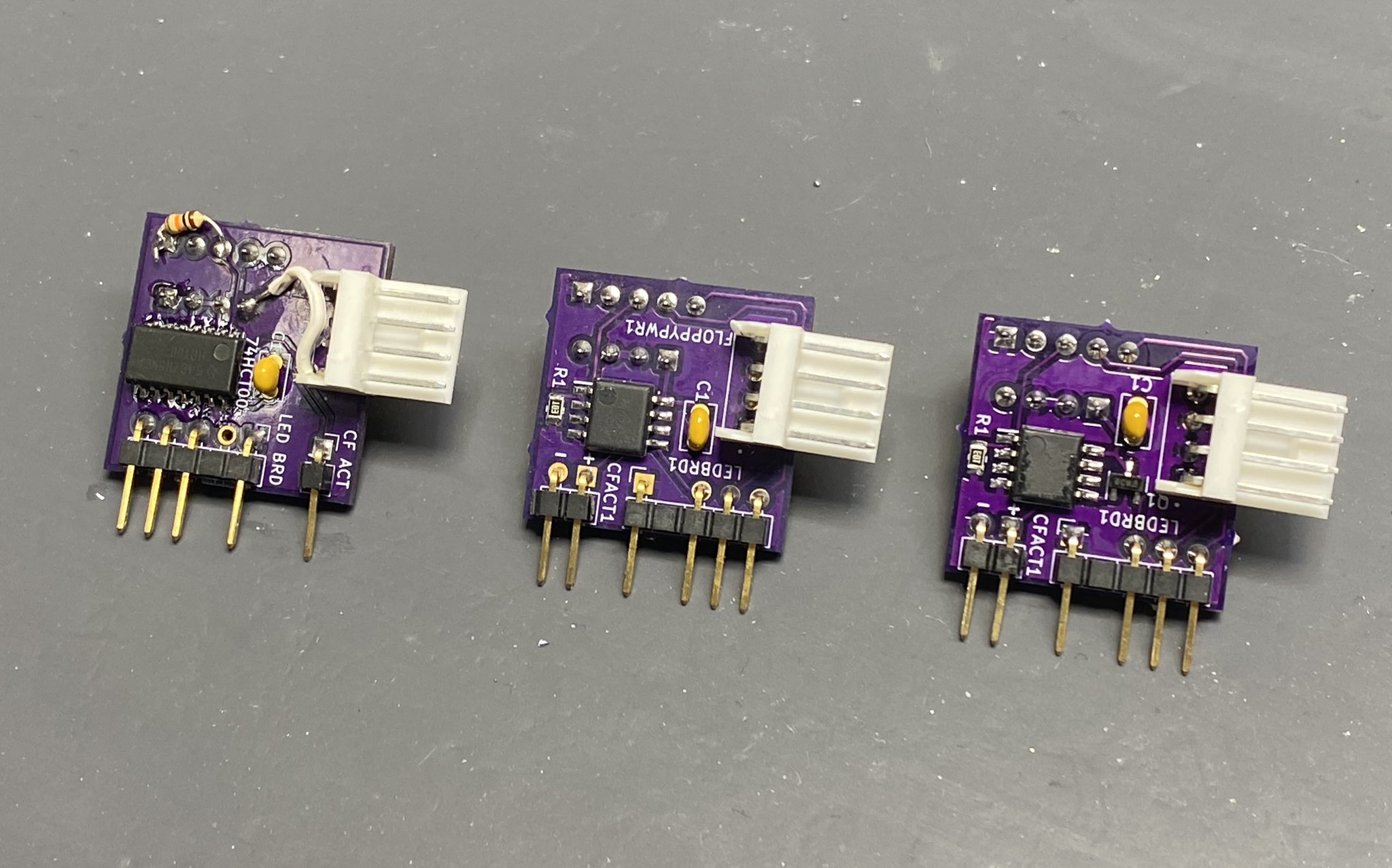
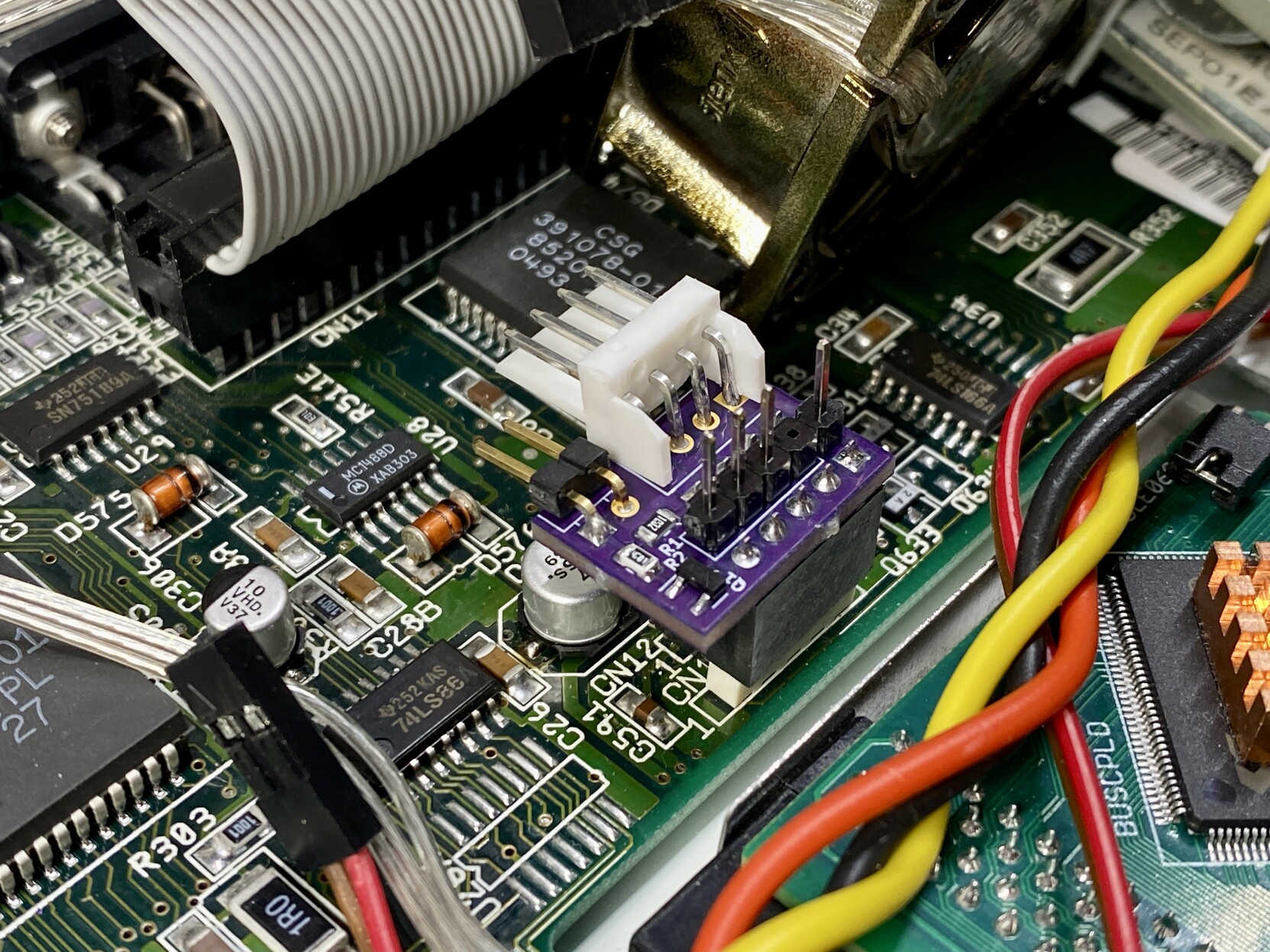
The final working design. It fits over the keyboard LED and floppy power headers on the A1200's motherboard:
Blinking:
PiGUS
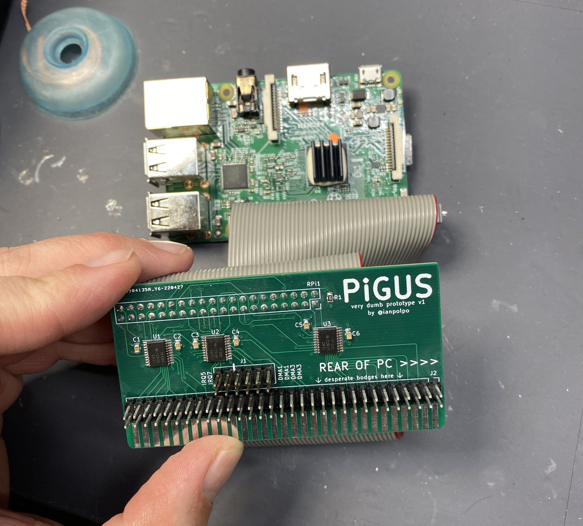
This was something that started off as what I called a "very dumb prototype" that turned out to work way better than I ever expected. The idea came into my head when watching Twitch streams by 48kRAM and djh0ffman and they both lamented the high cost of a Gravis Ultrasound card. The Gravis Ultrasound (GUS for short) was for a brief period in the early-mid 90s, the absolute best bang-for-the-buck sound card out there. It had 1MB of sample ram and could mix up to 32 channels of what it called wavetable synthesis. This allowed a normally CPU intensive task to be offloaded completely to the sound card, freeing up the system to focus on graphics and other things. The GUS was pretty good at MIDI playback, and it was used in quite a few games for that, but it really was embraced by the DOS demoscene. That's how I came to be interested in one back in the 90s, and I was fortunate to get one for Christmas one year. I still have my card, and it's working great after replacing its main brain, the GF1 chip. There are quite a few PC emulators that also emulate the GUS, like DOSBox, DOSBox-staging, DOSBox-X, PCem, 86Box, and MAME, so I figured I could use an existing GUS emulation core, run it on a Raspberry Pi, and plug it into an ISA slot with some level shifting ICs. I found a project on GitHub called RPiISA that was a bit simpler but was capable of emulating an AdLib card. Using that as inspiration, I designed the first prototype of what I called the PiGUS, waited for the PCBs to come, and then assembled it. I got the Raspberry Pi header backwards, so I had to attach it with a ribbon cable. Whoops!
After some hacking, I was able to get AdLib emulation working based on the RPiISA project. Then after some more hacking, I got the first glorious sounds of a Gravis Ultrasound, playing Purple Motion's Starshine in CapaMOD, a GUS-only module player.
I was frankly shocked. I didn't expect it to sound this good straight away. I hacked a bit and was able to add IRQ support, and got it to play X14, my all-time favorite DOS demo:
At this point, I posted about it on the VOGONS forum. The response was quite positive, with some tangents into "why didn't you just do it on an FPGA" (the answer: "I don't know Verilog"). A comment by user rasz_pl, however, changed everything. He said:
I assumed you would need pico RP2040 with PIO to respond fast enough. Add ~$2 8MB SPI PSRAM APS6404L and you could do any sound card emulation on pico
OMG. What if. The Raspberry Pi Pico is only $4, and you could actually buy them. Throughout 2022, getting a "full" Raspberry Pi was almost impossible without relying on a bot to notify you of availability or buying from a scalper. My initial goal of this project was to democratize access to the GUS, so why not base it on a microcontroller that was actually available and really cheap? The RP2040-Doom project showed that the Pico was capable of some incredible things, including emulating the OPL2 chip on an AdLib card. So I got going...
PicoGUS
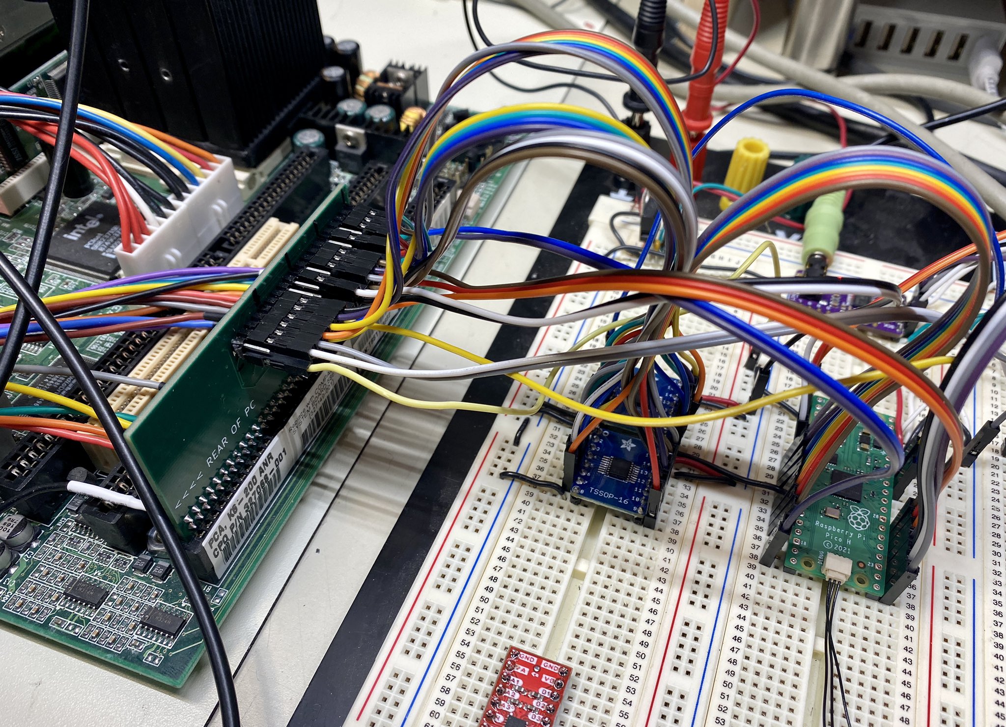
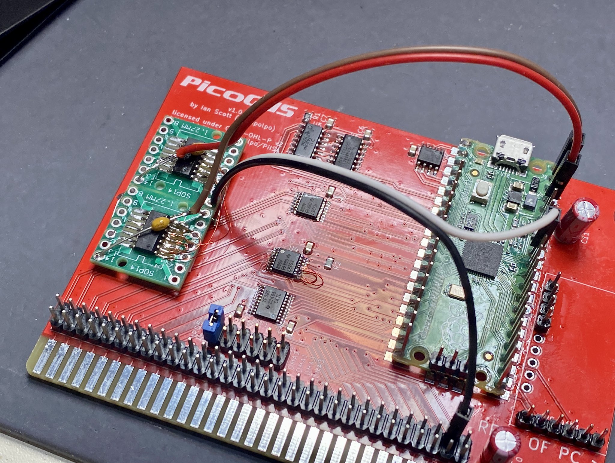
As a proof of concept, I started off by taking my original PiGUS board, and hanging a breadboard with mux/demux chips, Raspberry Pi Pico, and DAC module of it. I'd use this to learn about PIO (programmable IO) on the Pico's RP2040 microprocessor, an amazing state machine-based way to handle IO independent of the CPU. This PIO was going to be the key to making everything work.
After going though the "get port IO working" steps again on the Pico, I brought in the OPL2 emulation code from RP2040-Doom, and... it worked! AdLib emulation on the Pico!
Ok, this was feeling actually possible. I ran off and came up with a PCB design and sent it off to be made. I paid for express shipping because I really wanted to get things going for real with the Pico.
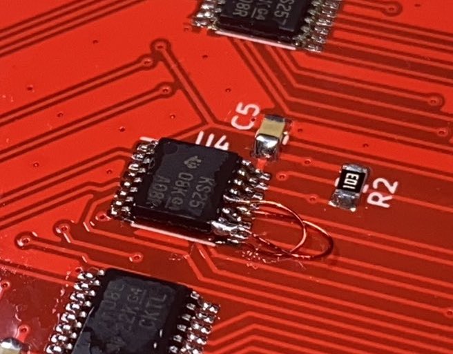
Because I was in such a rush, though, this board had numerous problems. A couple of the address/data lines were swapped, which I only realized after some very frustrating debugging. I had to do my smallest/fiddliest ever bodge, something I'm still really proud of:
A couple of the signal lines for the DAC also had to be changed around, due to the way the I2S PIO program in the pico-extras project drives the lines. So I had to hang the DAC module off of some Dupont wires instead of being directly on the board. After overcoming those hardware issues, I finally got going on GUS emulation. Port-only emulation wasn't too hard, and after settling on the GUS emulation core in DOSBox-X as a basis due to its eschewing of floating-point math, I got some promising results with chiptunes. Here's an example showing some stuttering audio at the end before I switched to DOSBox-X's emulation:
The RP2040 doesn't have enough RAM on board to emulate the full 1MB of RAM on the GUS, so I was limited to pretty small songs. The comment from rasz_pl mentioning SPI PSRAM was really important – with external RAM that only used a few pins for SPI, storing 1MB of samples would be no problem, as long as it was fast enough. I finally got things working, with a lot of effort. The timing requirements of the PSRAM chip are really fiddly – only a small mention noting that reads should happen on the falling edge of the SPI clock above 83MHz in the datasheet for one of the many variants of the PSRAM chip clued me in that I needed to handle things differently. I couldn't rely on the hardware SPI module on the RP2040, so I had to write a PIO program tailored to the odd timing. Fortunately, once I got things working, the speed was more than enough:
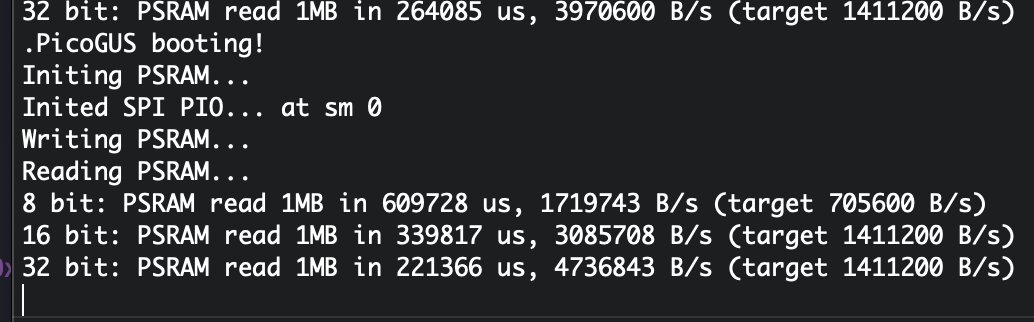
Once that was done, I could finally load songs with more than 100KB of samples!
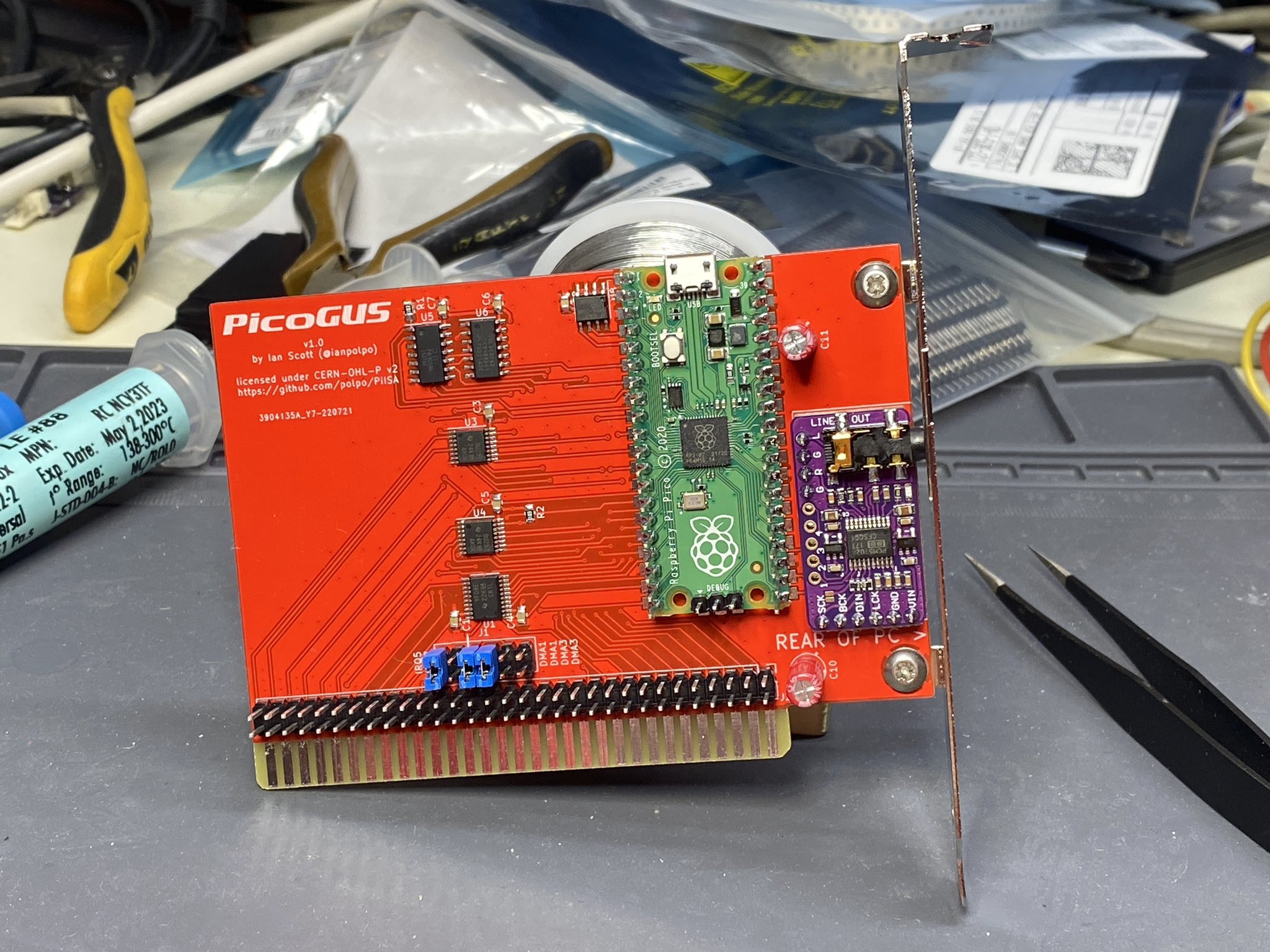
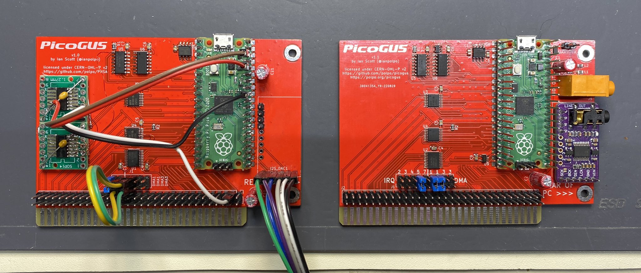
With this under my belt, I decided I needed to do another hardware revision, to change the swapped lines that I had to bodge, and get a few GPIOs back to get a dedicated UART out to help in debugging. And if I had a dedicated UART out, I could also use it for MIDI output. Hmm...! Learning my lesson from last time, I did my best to test these hardware changes before having another PCB manufactured. More bodges appeared on the v1 PCB, mostly to implement the new reset logic and handling of the DACK signal to save on precious PIO instructions:
After getting this "final" PCB design, I was feeling pretty good with it. Unfortunately, progress really, really slowed down. Getting reliable IRQs was eluding me, and I had a feeling that DMA was going to be even harder to nail down...
At this point, I decided I was at a good enough milestone, and made a nice video showing the progress, with high quality captures of demos and other programs running on a system with a PicoGUS:
IRQs were hard, but I eventually figured out what the problem was: a race condition between timer IRQs and wave IRQs. The GUS can trigger an IRQ for three reasons: when a set timer expires, when wave playback reaches a set point, and when a volume ramp reaches a set point. After a lot of flailing about, I came across a 95% good enough fix - reducing the audio buffer size significantly! Wave and volume IRQs would trigger at the end of rendering the audio buffer, and increasing the frequency in which those IRQs could happen helped a ton. I made another video showing the improvements this made, but there were a few regressions with IRQs in programs that were working fine before.
Unfortunately, literally hours after I posted this video, a family emergency occurred that would wind up taking up a large part of my time for the following month. I did work on things to distract myself here and there, but progress was spotty. Everything I tried to stamp out the regressions were fruitless, until I finally came to a solution – using critical_section to wrap IRQ status updating and IRQ firing in a spinlock. These events can happen on either core, and this was finally a way to get things under control. I was super happy, wrapped up work on the fixes and made a new software release on the PicoGUS GitHub project.
After a couple more days work, even more things were working, and amazingly, my buggy DMA code was working far, far better! It actually worked with some games like Star Control II. I came out with another software release and made a quick update video for #DOScember:
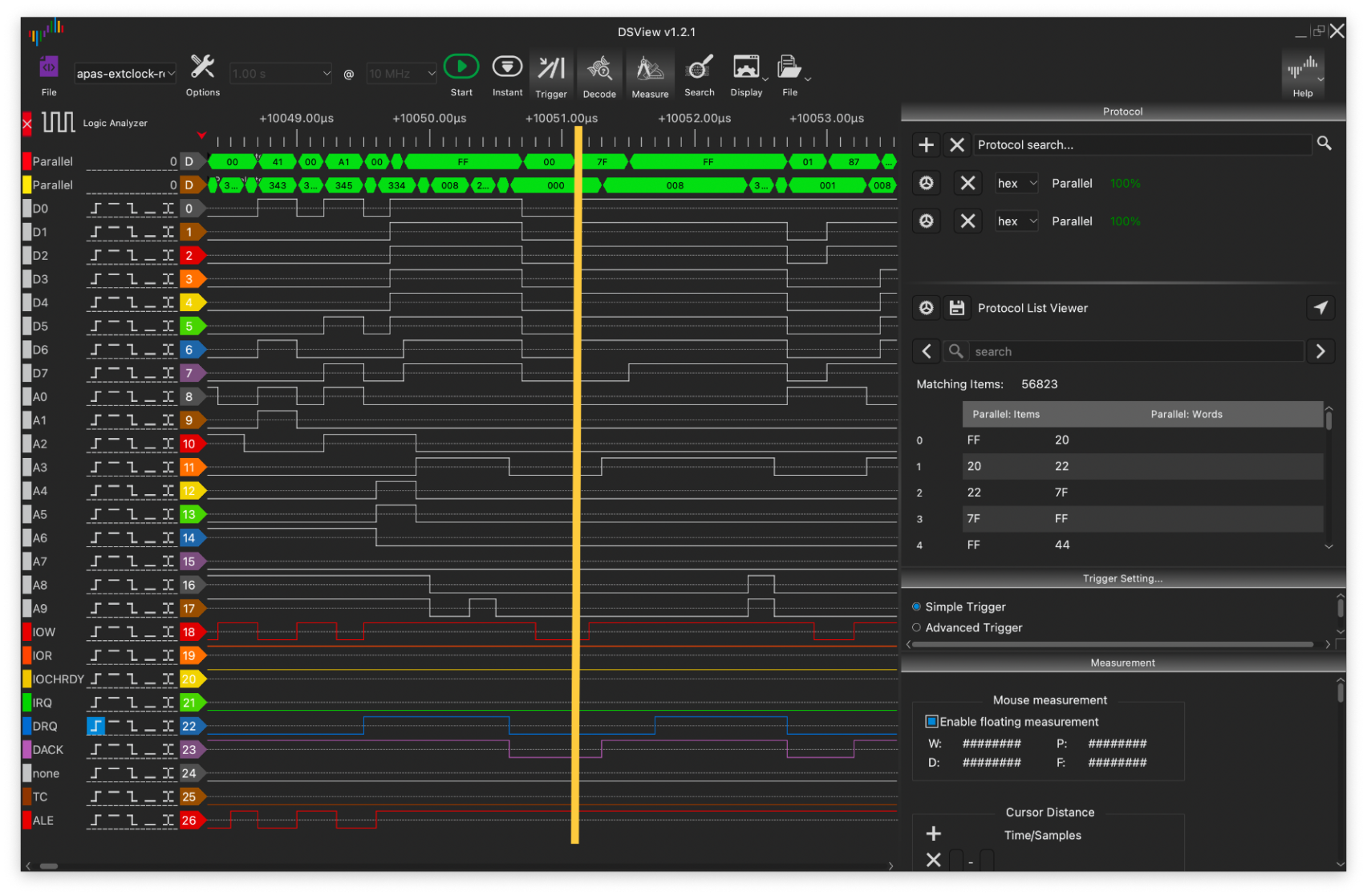
Now, I am tackling the issues with DMA. The first issue I found is that data is valid on the data pins only on the rising edge of DACK – this significantly limits the time to respond to each DMA event, and there's basically no time to raise IOCHRDY to slow DMA events down. Here's a shot from my logic analyzer showing when data is valid, which is along the orange line. It disagrees with almost all DMA timing diagrams I've been able to find!
The primary reason is that port IO events can happen in between the GUS raising DRQ to start a DMA transaction and the system returning back with DACK to acknowledge and actually start the DMA transfer. The short time window due to the above timing issue, the slow speed of handling certain IO events, and high latency of writing to PSRAM really make this challenging. I'm currently away for a couple weeks for the holidays, but I'm still hacking on this problem. I have a minimal Pico development setup, and I have what I think will solve the DMA issue: more DMA! I can use DMA on the RP2040 to send data to the PSRAM chip's PIO state machine asynchronously with no CPU involvement, leaving it free to handle IO events in the middle of a DMA transaction. I have it working on my minimal setup. In the new year, we'll see how it behaves in a real computer. Fingers crossed!
You can find PicoGUS's hardware design files and firmware at the PicoGUS GitHub repository.
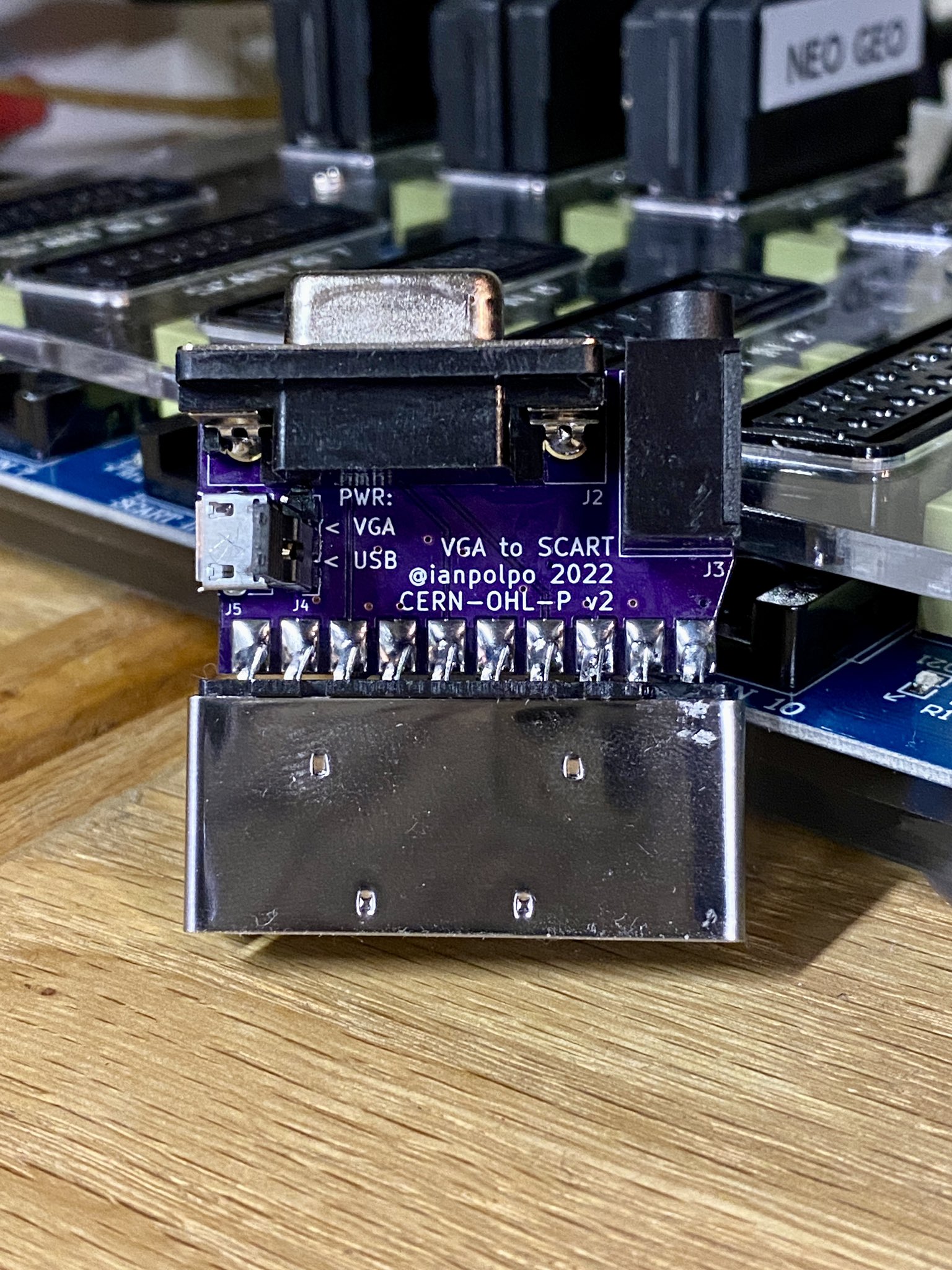
VGA-SCART adapter
I recently got a nifty 10-port SCART switcher for my gaming console area, and the one oddball in my console collection that didn't have a way to output RGB over SCART was my Dreamcast which uses VGA. I hunted around for ways to convert VGA to SCART and found this design from Mike Chi of RetroTINK fame. It uses an XOR logic chip to do the sync combining and seems to work well. The only problem is that his board is fairly large, and I wanted something that would fit on the head of a SCART connector. Also, many Dreamcast VGA cables don't put 5V on pin 9 of the VGA connector, so I added a jumper to allow it to be powered from a micro USB connector. This current design needs a bodge to put voltage on the right pin to get my SCART switch to switch, so I've put off putting this design up on GitHub.
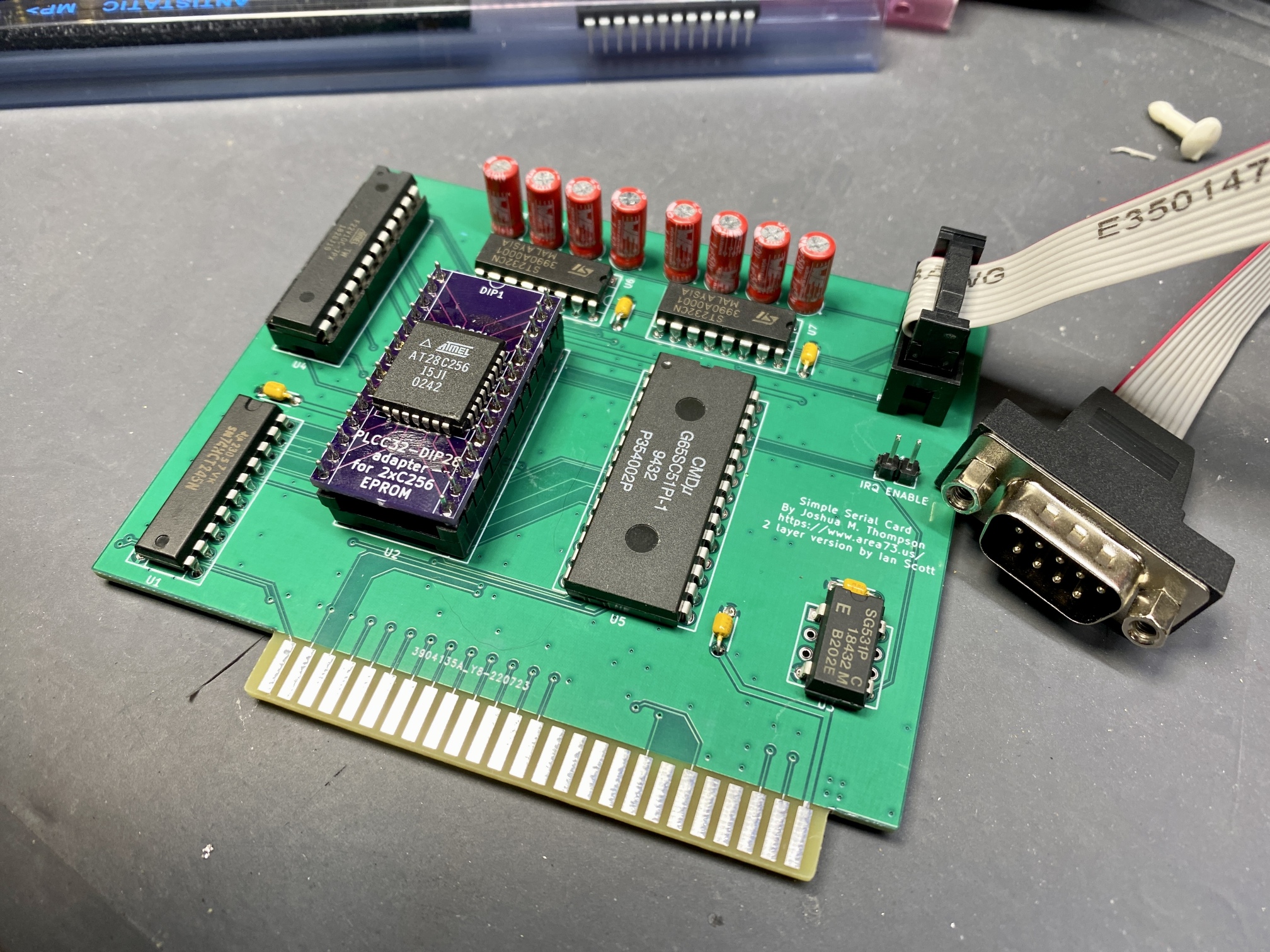
Apple II Super Serial Card
I also got an Apple IIe and wanted a way to easily create new disks with ADTPro. The Super Serial Card is one of the ways that ADTPro can connect, but original ones go for quite a bit on eBay. I found this project on GitHub which is a reverse engineered and simplified version of the card. That design is on a 4-layer board but it's pretty simple so I made a 2-layer version so I could get 5 boards made for $2 at JLCPCB. The board uses several obsolete components, but I was able to source pretty much all of them from an eBay seller in my town that offers local pickup, so that was cool!
The board works fine in ADTPro, but there are some serious issues with using its built-in ROM. After finding some discussion on the VCF forums about it and a related GitHub issue, it looks like there are some issues with the GAL equations that replace some of the discrete logic chips in the original SSC design. I attempted rewriting the GAL equations after peering at the schematics for the original SSC but my new GAL equations and changes to the code in the ROM by user btb haven't been enough to solve the issue. So this project is on the back burner for now. A more faithful reverse engineering or a complete emulation of the card on a Pi Pico may be the best way forward for this.
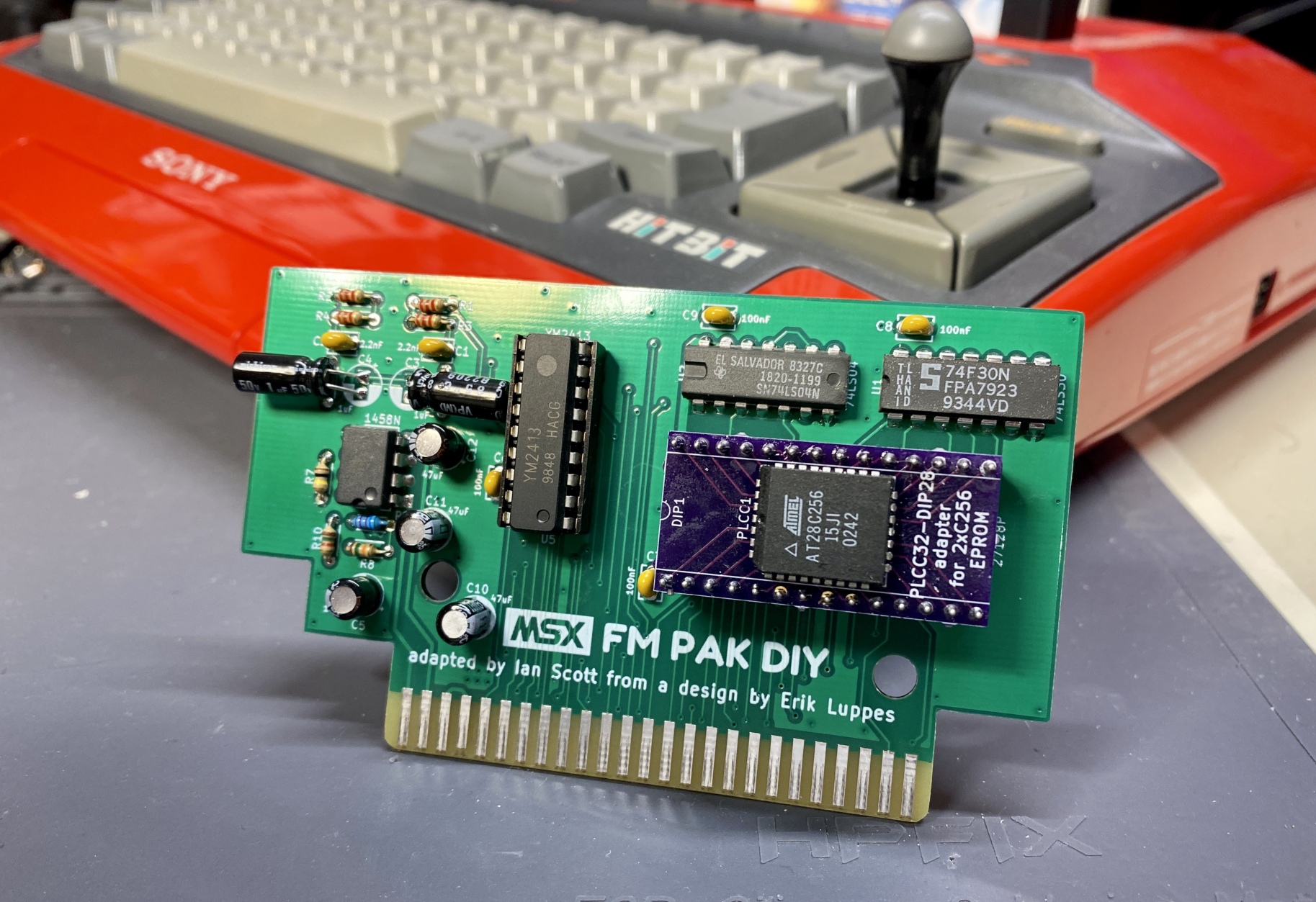
MSX FM PAK DIY
A post by Inverse Phase on Mastodon got me really interested in the capabilities of the rather limited Yamaha YM2416 OPLL FM synthesis chip and its use on the MSX series of computers. There are several cartridges that include the YM2416, from the original Panasonic FM-PAC cartridge, to several reverse engineered options that retail for 50EUR or more which would have to be shipped from Europe. I decided to make my own YM2416 board for the MSX, and found a design by Erik Luppes for one. After reading a thread on MSX.org about it, I decided to change his design a bit to avoid some the audio noise issues mentioned in the thread. This was mostly adapting the layout a bit to avoid having the analog traces crossing all the way across the board, and making the PCB fit in a Konami style cartridge shell. I decided to call it the "FM PAK DIY" because I wanted to make the design DIY friendly. I had it made and it sounds really good, except in my Sanyo Wavy23 MSX2 machine, which has known issues in its cartridge expansion audio circuit. This is another one of my projects that I'd like to get up on GitHub, but the license situation for the original design is a bit unclear to me and I'd like to get it right.
Conclusion
Oh man, this post was a lot longer than I was expecting. I hope I can keep this up in the next year. Despite a lot of challenges in 2022, this has been some of the most fulfilling my "random retro tinkering" hobby has become. If you made it this far, thanks for reading! If you want to keep up with what I'm doing outside of these longer-form posts, I post on Mastodon at @polpo@bitbang.social.
Also, PicoGUS has spawned a few other projects: PicoMEM from FreddyV and a Pico PCMCIA project from yyzkevin. We talk on a new Discord server called Retro Pico Hardware and offer each other support and encouragement. If you'd like to see what we're up to and to help out with anything, feel free to join on the link above.